

Design and Installation
Use mechanical safety disconnects for feeder circuits
A contactor, circuit breaker, or mechanical disconnect should be used ahead of the fusing and SCR power controller to serve as a mechanical safety disconnect. Outputs of SCR power controllers are live whenever voltage is present on the controller inputs!
Verify orientation for natural convection cooled power controllers.
Passively cooled SCR power controllers rely on natural convection. The controller needs to be oriented so the cooling fins run vertical in order to dissipate the rated heat properly. Failure to do so will shorten the life of the SCR and may cause an unintended system shutdown.
Keep contactors upstream of an SCR
Always keep contactors upstream of the SCR power controller to prevent damaging voltage kickback during opening of the contacts.
Size current of power controllers and load for the lowest voltage your facility may see.
Dips in facility power may cause your power controller to run at a higher current output than planned in order to achieve the desired power output. This may also lead to extra heat load within the electrical enclosure.
Understand certification requirements at your customer’s location.
Check with your customer to verify local code requirements before planning your electrical panel. If the final destination is within the US, pay special attention to Short Circuit Current Rating (SCCR) and available fault current at the facility. SCR power controllers require specific design considerations in order to meet SCCR requirements in the panel.
Protect the controller from dust, metal shavings, or screws
During system installation, small metal shavings can drop into the top of the controllers. This may cause short circuits or arcing. Cover the unit or wait to mount controllers until holes have already been drilled in the enclosure.
Check system thoroughly after installation and mounting
Make sure all lugs are torqued to proper torque specifications. Inspect for frayed wires. Follow recommended strip length for terminals.
Test all system fault and recovery scenarios during startup
Verify system design is capable of handling and recovering from all fault scenarios:
- Overcurrent Trip
- Communications failure
- Over temperature
- Shorted SCR
- Phase lock
- Phase loss (3 Phase)
- Load imbalance (3 Phase)
- Limits: voltage, current, or power
Fusing and Transformers
Fusing
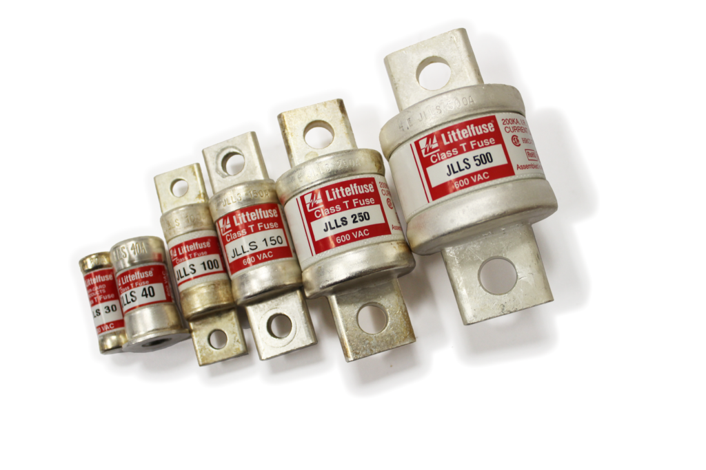
Use High Speed Class J or Class T fuses to avoid nuisance tripping
Size fuses with the formula: 1.25 x SCR frame rating (Amps)
- Phase Angle: Select closest standard fuse size.
- Zero Cross: Select next largest size.
Fuse all legs
For single phase loads, fuse both legs. For three phase loads, fuse all three legs, regardless of whether it is 2-leg or 3-leg control.
Transformers
Use contactors upstream of the SCR
If the SCR is being used to control the primary of a transformer, there should be no contactors between SCR and the primary of the transformer as well as no contactors on the secondary.
SCRs do not parallel or load share.
i.e. You cannot use two 50A controllers in parallel to power a 100A load. Either split the load into two 50A loads, or use a single 100A power controller.
Isolation transformers with electrostatic shields are recommended.
An electrostatic shield will shunt the capacitive coupling across the transformer and prevent common mode line voltage to ground on the transformer outputs. Without the shield, you may see line voltage potential with up to several hundred milliamps of current on the output taps.
Maintain a minimum load
When firing into a transformer, maintain a minimum load of 1 amp on the primary to prevent a misfire and saturation of the transformer. A dummy load may be required to maintain proper operation for inductive loads or magnetrons.
Environmental Conditions
Confirm adequate clearance around the controller for air flow.
A three inch clearance above and below the controller is required.
Check the temperature of the air surrounding the controller
Size enclosure and provide adequate cooling so that the air surrounding the controller does not exceed its thermal rating. Use an enclosure heater if the environment can reach below 0 degrees C. SCRs require more gate current as the temperature decreases and will eventually exceed the drive capability causing a misfire.
Prevent radio interference
SCR power controllers are susceptible to radio interference from hand held radios and repeaters and can potentially misfire during radio transmissions. Keep the controller in a metal enclosure to prevent radio interference. Use grounded metal screen mesh over air louvers and cabinet openings to prevent radio signals from interfering with your equipment.
Use a grounding rod in noisy environments
This may be beneficial if you have a bad system ground.
Use a sealed or positive pressure enclosure for dirty, oily, dusty, or conductive dust environments
For heavy dirt or dusty environments, a sealed cabinet with air conditioning or filters is recommended. A sealed or positive pressure enclosure is required if placed into a conductive dust environment such as graphite or carbon.
De-rate controller for installations above 6000 feet.
As the air thins at increased elevations, natural convection and forced air cooling becomes less efficient. Follow the manufacturer’s recommendations for de-rating the SCR power controller above 6000 feet altitude.
Control Concepts power controllers are designed for continuous full-frame current operation without derating up to 122°F [50°C], 6000 ft [1829 m] altitude.
Control Concepts Can Help
Our team of experts at Control Concepts can help you design a system that fits your application using reliable, high performance, and cost-effective SCR power controllers. Contact us to learn how we can help power your process.