
Power quality affects nearly every aspect of industrial operations. From energy costs and equipment performance to system reliability and production uptime, the way electrical power is delivered and consumed has a direct impact on business performance.
Two of the most important concepts in power quality are power factor and harmonics.
These terms are often discussed together because they influence how efficiently electrical systems operate. However, many engineers and facility managers still treat them as separate issues. In reality, power factor and harmonics are closely connected, and understanding their relationship is critical for maintaining reliable industrial power systems.
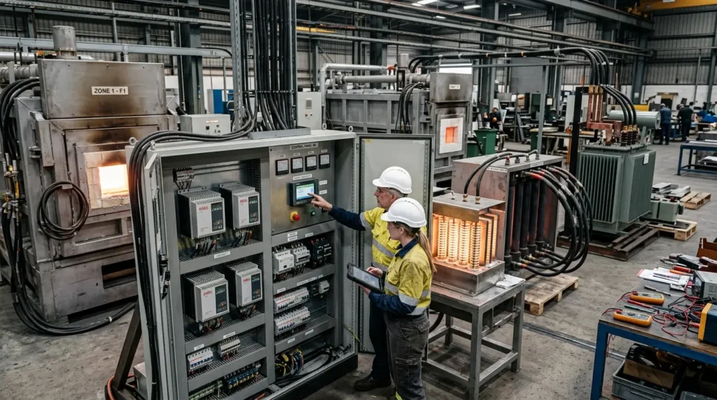
Whether you operate heat treating furnaces, semiconductor equipment, industrial ovens, water treatment facilities, or manufacturing lines, this guide explains what power factor and harmonics are, why they matter, how they affect each other, and what steps can be taken to improve overall power quality.
What is Power Factor?
Power factor is a measurement of how effectively electrical power is converted into useful work. In an ideal system, all electricity supplied by the utility is used to perform productive work. In reality, some of that power is lost or temporarily stored within electrical equipment.
Power factor is expressed as a number between 0 and 1. A power factor of:
- 1.0 indicates perfect efficiency
- 0.95 is generally considered very good
- 0.80 or lower often indicates a power quality issue
The closer power factor is to 1.0, the more efficiently electricity is being used. Understanding power factor starts with understanding three different types of electrical power: real power, reactive power, and apparent power
| Power Type | Symbol | Unit | Description | Examples |
|---|---|---|---|---|
| Real Power | kW | Kilowatts | Performs useful work | Heating elements producing heat Motors driving equipment Pumps moving fluid |
| Reactive Power | kVAR | Kilovolt-amperes reactive | Supports electromagnetic fields required by inductive devices | Motors Transformers Inductors |
| Apparent Power | kVA | Kilovolt-amperes | Total power supplied by the source |
The relationship is often represented as Power Factor = kW ÷ kVA. Thus, as apparent power increases relative to real power, power factor decreases.
Why Power Factor Matters
Poor power factor creates inefficiencies throughout an electrical system. Consequences can include:
- Higher utility charges
- Increased current draw
- Larger conductor requirements
- Transformer loading issues
- Excess heat generation
- Reduced system capacity
- Lower overall efficiency
Many utilities impose power factor penalties when facilities operate below specified thresholds because poor power factor increases stress on the electrical grid. For large manufacturing facilities, even a small improvement in power factor can generate meaningful cost savings over time.
Displacement Power Factor vs True Power Factor
Displacement power factor measures the phase relationship between voltage and current at the fundamental frequency. It is the traditional power factor measurement associated with inductive loads.
True power factor includes both phase displacement effects and harmonic distortion effects. Because harmonics increase distortion, true power factor is often lower than displacement power factor. This difference is particularly important in facilities using significant amounts of power electronic equipment.
True Power Factor = Displacement Power Factor × Distortion Factor
What Are Harmonics?
Harmonics are voltage or current waveforms that operate at multiples of the fundamental electrical frequency. In North America, the standard frequency is 60 Hz. Instead of maintaining a smooth sinusoidal waveform, harmonic-producing equipment distorts the electrical signal. This distortion can create numerous power quality problems throughout a facility.
| Harmonic Order | Frequency |
|---|---|
| Fundamental | 60 Hz |
| 3rd Harmonic | 180 Hz |
| 5th Harmonic | 300 Hz |
| 7th Harmonic | 420 Hz |
| 11th Harmonic | 660 Hz |
What Causes Harmonics?
Harmonics are generated by non-linear electrical loads. Unlike traditional resistive loads, non-linear devices draw current in irregular pulses rather than smooth waveforms. Common harmonic sources include:
- Variable frequency drives (VFDs)
- SCR power controllers
- Rectifiers
- DC power supplies
- UPS systems
- Industrial automation equipment
- Battery charging systems
- LED lighting systems
- Semiconductor manufacturing equipment
- Welding equipment
As industrial facilities adopt more power electronics, harmonic distortion becomes increasingly common.
What Is Total Harmonic Distortion (THD)?
Total Harmonic Distortion (THD) measures the amount of harmonic content present in an electrical waveform. THD is typically expressed as a percentage.
Higher THD levels indicate greater waveform distortion. Excessive distortion can negatively affect equipment performance and reliability.
| THD Level | Condition |
|---|---|
| Less than 5% | Excellent |
| 5% – 8% | Acceptable |
| 8% – 10% | Requires monitoring |
| Greater than 10% | Potential concern |
Common Problems Caused by Harmonics
Excessive harmonic distortion can affect nearly every component connected to the electrical system.
Transformer Overheating
Harmonic currents create additional losses within transformers, leading to higher operating temperatures, reduced efficiency, and shortened lifespan.
Cable Heating
Conductors carrying harmonic currents may experience additional heating, resulting in increased energy losses, reduced cable life, and higher operating temperatures.
Nuisance Tripping
Circuit breakers and protective devices may respond unexpectedly when harmonic levels become excessive. Common symptoms include false alarms, unnecessary shutdowns, and reduced process uptime.
Equipment Reliability Issues
Sensitive equipment may experience communication errors, control instability, reduced performance, or premature component failure.
SCR Controllers and Harmonics
SCR power controllers are widely used throughout industrial heating applications for precise and responsive power control. Applications range from heat treating and semiconductor manufacturing to environmental chambers, glass production, industrial ovens, and more. Regardless of the application, the firing method used by an SCR controller can significantly affect harmonic generation. The magnitude of the harmonics are the greatest when the load power is controlled at 50%.
Phase Angle Firing
Phase Angle firing adjusts power by controlling the point at which SCRs conduct during each AC cycle. Advantages include fast response, precise power control, and excellent process stability. However, Phase Angle firing can generate harmonic currents because this mode modifies the sinusoidal waveform.
Zero Cross Firing
Zero Cross firing switches power at natural voltage crossing points. Benefits include reduced harmonic generation, improved power quality, and lower electrical noise. Many industrial heating systems use Zero Cross firing when minimizing harmonics is a priority.
Comparison of Harmonics in Phase Angle and Zero Cross Control
| Zero Cross | Phase Angle | ||||
| Harmonic | Frequency (Hz) | Magnitude (%) | Harmonic | Frequency (Hz) | Magnitude (%) |
|---|---|---|---|---|---|
| 1 | 10 | 10.90 | 1 | 60 | 59.70 |
| 2 | 20 | 0.00 | 2 | 120 | 0.00 |
| 3 | 30 | 14.10 | 3 | 180 | 31.80 |
| 4 | 40 | 0.00 | 4 | 240 | 0.00 |
| 5 | 50 | 34.71 | 5 | 300 | 10.60 |
| 6 | 60 | 50.00 | 6 | 360 | 0.00 |
| 7 | 70 | 29.80 | 7 | 420 | 10.60 |
| 8 | 80 | 0.00 | 8 | 480 | 0.00 |
| 9 | 90 | 8.49 | 9 | 540 | 6.40 |
| 10 | 100 | 0.00 | 10 | 600 | 0.00 |
| 11 | 110 | 4.50 | 11 | 660 | 6.40 |
| 12 | 120 | 0.00 | 12 | 720 | 0.00 |
| 13 | 130 | 2.88 | 13 | 780 | 4.60 |
| 14 | 140 | 0.00 | 14 | 840 | 0.00 |
| 15 | 150 | 2.03 | 15 | 900 | 4.60 |
| 16 | 160 | 0.00 | 16 | 960 | 0.00 |
| 17 | 170 | 1.50 | 17 | 1020 | 3.50 |
| 18 | 180 | 0.00 | 18 | 1080 | 0.00 |
| 19 | 190 | 1.18 | 19 | 1140 | 3.50 |
| 20 | 200 | 0.00 | 20 | 1200 | 0.00 |
| 21 | 210 | 0.09 | 21 | 1260 | 2.90 |
| 22 | 220 | 0.00 | 22 | 1320 | 0.00 |
The Relationship Between Power Factor and Harmonics
One of the most misunderstood aspects of power quality is the relationship between power factor and harmonics. Many people assume power factor is affected only by inductive loads such as motors and transformers. While this assumption was largely true in older facilities, modern industrial systems often experience reduced power factor due to harmonic distortion. This distortion occurs because harmonics increase apparent power without contributing useful work.
As a result, apparent power increases, true power factor decreases, and system efficiency drops
This means a facility can have acceptable displacement power factor while still experiencing poor true power factor because of harmonic distortion.
Can Power Factor Correction Create Harmonic Problems?
Yes. One of the most common mistakes in industrial power quality management is installing capacitor banks without considering harmonics. Power factor correction capacitors can interact with harmonic frequencies and create resonance conditions. Potential consequences include amplified harmonic distortion, capacitor failures, overheating, or equipment damage. These consequences are why power factor correction projects should always include harmonic analysis.
Harmonic Mitigation Strategies
Successful power quality programs address both power factor and harmonic distortion simultaneously. Several mitigation methods exist, from active and passive filters to isolation transformers and proper controller selection.
Active Harmonic Filters
Active filters continuously monitor the electrical system and inject corrective currents to cancel harmonics. Benefits include dynamic response, multi-frequency filtering, and improved flexibility. These systems are increasingly popular in facilities with varying loads.
Passive Harmonic Filters
Passive filters use combinations of capacitors, reactors, and inductors to target specific harmonic frequencies. These filters are a proven technology with lower cost and reliable operation.
Isolation Transformers
Isolation transformers can help reduce the propagation of harmonic currents throughout a facility. They are commonly used in semiconductor manufacturing, data centers, and critical process applications.
Proper SCR Controller Selection
The choice of firing mode can significantly affect harmonic performance. When evaluating SCR systems, engineers should consider the following system features:
- Load characteristics
- Process requirements
- Utility requirements
- Harmonic limits
- Power quality objectives
Proper application design often reduces harmonic concerns before they become significant problems. Although harmonics are a common concern, very few if any problems have occurred in actual application. This is because harmonics are attenuated by inductance, and because the effects of harmonics are attenuated by proper shielding and grounding of electrical equipment.
How to Improve Power Quality
Organizations that maintain strong power quality programs often follow several key practices.
1. Monitor Power Quality Regularly: Routine measurements help identify developing problems.
2. Evaluate Harmonics Before Installing Capacitor: Power factor correction should never be implemented without harmonic analysis.
3. Review Equipment Specifications: Power electronic devices should be evaluated for their harmonic impact.
4. Use Appropriate SCR Firing Modes: Application requirements should guide controller selection.
5. Conduct Periodic System Audits: Electrical systems evolve over time. Regular reviews help maintain long-term reliability.
Control Concepts Supports Power Quality Performance
Control Concepts designs SCR power control solutions for industries where thermal precision, reliability, and electrical performance are critical. Our solutions support:
- Semiconductor manufacturing
- Heat treating
- Environmental chambers
- Glass production
- Composite curing
- Chemical processing
- Water treatment
- Industrial heating applications
By selecting the appropriate SCR technology, firing method, and control strategy, manufacturers can achieve better process performance while supporting broader power quality objectives.
Frequently Asked Questions
Power factor measures how effectively electrical power is converted into useful work. A higher power factor indicates more efficient use of electricity.
Harmonics are electrical frequencies that occur at multiples of the fundamental frequency and distort normal voltage and current waveforms.
Some SCR firing methods, particularly Phase Angle firing, can generate harmonic currents. The level depends on the application and firing strategy.
Many facilities target THD levels below 5%, although acceptable limits vary by application and industry standards.
Common solutions include passive filters, active filters, proper equipment selection, harmonic analysis, and optimized power control strategies.
Improve Your Facility’s Power Quality
If your operation is experiencing poor power factor, harmonic distortion, transformer overheating, or unexplained power quality issues, evaluating your power control strategy may be the first step toward improvement.
Control Concepts helps manufacturers identify SCR power control solutions that support process performance, electrical reliability, and long-term operational efficiency.